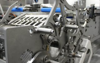
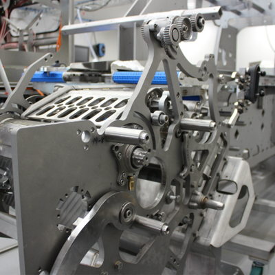
Metal 3D Printing is Spicing Up Food & Beverage Equipment
Desktop Metal has compiled the top 5 reasons we see the food and beverage industry moving to metal 3D printing. While mentions of 3D printing for food may bring to mind chocolate extruded into cool decorative shapes, additive manufacturing is actually transforming the industry behind the scenes – making food and beverage processing equipment safer, more productive, and delivering all-new innovations to the nearly $60 billion industry. If you’ve ever watched an episode of “How it’s Made” on Discovery TV, you’ve seen the complexity of cleaning, cutting, mixing, swirling, layering, stretching, shaping, or molding of food or beverages in solid, semi-solid, or liquid states. And that’s all before they get packaged by complex assembly lines that often resemble a Rube Goldberg machine. In all, the food and beverage industry is a symphony of hundreds of thousands of complex mechanical parts and assemblies that perform tasks that must also meet strict standards for quality and sanitization. Metal parts, often made of stainless steel, are an industry standard material for that safety reason. But making and shaping all of those complex metal parts comes with challenges, and this is where 3D printing, also known as additive manufacturing, offers value-added solutions. Building parts layer-by-layer eliminates many [...]
A Tribute to Mike Sljaka
The Cimquest family woke up on Monday, Mar 13, 2023, to the news that our beloved colleague and friend, Michael Sljaka, had succumbed to his longtime battle with cancer on Saturday, March 11th. Mike worked for Cimquest as a Senior Applications Engineer since the acquisition of Services Four Automation in October of 2011 where he worked since August 2007. Mike quickly became popular with customers and his fellow colleagues. He put in countless hours to provide a high level of customer service. His responsibilities ranged from Mastercam applications and training to CNC programming to being an integral part of the 2-Minute Tuesday video series. Every task that Mike was involved in had the highest dedication to quality which he encouraged in others. He was the epitome of “If you are going to do something - do it right!” Mike was the best colleague a person could ask for and an inspiring key member of our Mastercam Team. He was very supportive and motivating as a co-worker and we always looked to him for his creative thoughts and ideas. But more than a wonderful colleague, Mike was an amazing person and friend. He was smart, funny, kind, deep, always ready to lend a helping [...]

Cimquest Adds Meltio to Their 3D Printing Lineup
Cimquest Becomes Meltio’s Official Sales Partner Cimquest is going to play a key role in the distribution and support of the Meltio metal 3D printing solutions in the North Eastern United States market, as an official sales partner. Meltio offers a pioneering metal 3D printing solution that enables industrial applications with a process built around welding wire, the safest, cleanest, and most affordable metal feedstock in the market. Cimquest will focus on building a supportive ecosystem for Meltio’s technology in the North Eastern United States territory partnering and driving business opportunities alongside technology centers, tooling machine companies, robotic integrators, academia, and industry. Rob Hassold, CEO at Cimquest says: "Cimquest is excited to partner with one of the top growth leaders in Metal Additive. We feel that the DED process fits well within our job shop customers' workflow and environment. The Meltio technology offers unique advantages compared to other metal printing technologies and will help to round out our metal additive offerings." Meltio proudly announces its first official sales partner in the North Eastern United States territory, Cimquest. Michael Humphrey, Sales Manager for North America at Meltio says: “We are thrilled to be working with companies like Cimquest as their expertise as well as [...]

Metrology Minute – Batch Processing
Control X is a powerful metrology product with dozens of inspection tools available including; 2D and 3D dimensioning, GD&T analysis, color maps, Whisker plots, and many more. After all of the inspection tools are deployed for a specific inspection plan, you can create a date and time-stamped report, serialized for a particular part scan. This ensures that the inspection report of a single-part scan against a nominal CAD model is correctly identified and stored. But how does this process work when you have 10, 100, or even 1,000 scans to inspect against the same nominal CAD model? Repeating the inspection process manually over and over again would be extremely time-consuming, not to mention very tedious. This is where the Control X Batch Processing comes into play! Batch processing is a workflow in Control X whereby you can launch an unmanned inspection process to be applied to as many part scans as required. How Does Control X Batch Processing Work? First, you prepare the inspection for the very first manufactured part scan. All of the inspection tools are deployed and applied to that very first part scan, including the all-important Initial Alignment followed by a Datum Alignment. The idea being the Initial Alignment will [...]
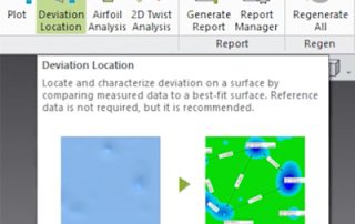
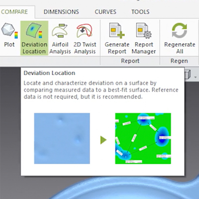
Deviation Location Tool in Control X
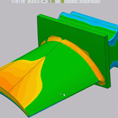
Today’s post will cover the Deviation Location tool in Geomagic Control X. This tool creates a Best Fit Surface over an area of interest and enables you to analyze isolated areas on a part for wear, dents, bumps, corrosion, etc. While Reference Data is not required for this function, it is recommended. This tool takes measurements in an isolated location of the part and requires the existence of either a coordinate system or two vectors that will be used to form a Coordinate System. The first step for using this function is to identify the two vectors or the coordinate system. Once the coordinate system is identified, you can specify the coordinate plane relative to those two vectors, or in our case, to the predefined coordinate system. Check for wear on the mounting and on the flat surface of the pump cover and after selecting the two flat areas of interesting geometry in question, hit the Apply button. The two selections on the Measured data will then be displayed. Please note that in order to control the scope of the size of the dent or deformation, you can use the slider called Local Search Scope. If you only need to identify smaller dents, [...]
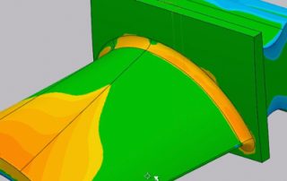
Analyzing Airfoil Shapes With Control X Airfoil Analysis
Today’s blog post will show you that analyzing airfoil shapes is easier than ever using the Geomagic Control X Airfoil Analysis technology. Once you complete an airfoil scan and align with the nominal CAD model, the software is able to return dozens of useful parameters. These parameters are necessary for a complete airfoil analysis and some of them include: Leading and trailing edge radii Leading and trailing edge positions in space Maximum chord height Leading (and trailing) Edge position in space relative to the model origin Axial chord length Additionally, leading and trailing edge thicknesses, as well as maximum airfoil thickness across the widest section, may be easily requested by using this powerful tool. This makes completing airfoil analysis simple requiring only a few clicks of the mouse. Furthermore, analyzing airfoils often requires identifying points along a section’s periphery and comparing those to the corresponding points from the nominal CAD model. Deploying the Comparison Point function in Control X, this too is handled by just a click or two of the mouse. Please check out our Control X – Comparison Point Analysis video to learn more about how that tool can be utilized. As you can see, Geomagic Control X continues to deliver [...]