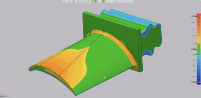
Today’s blog post will show you that analyzing airfoil shapes is easier than ever using the Geomagic Control X Airfoil Analysis technology. Once you complete an airfoil scan and align with the nominal CAD model, the software is able to return dozens of useful parameters. These parameters are necessary for a complete airfoil analysis and some of them include:
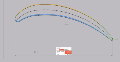
Leading and trailing edge radii
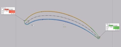
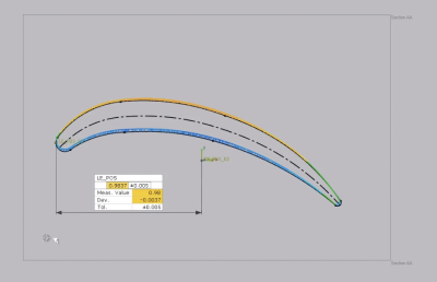
Leading and trailing edge positions in space
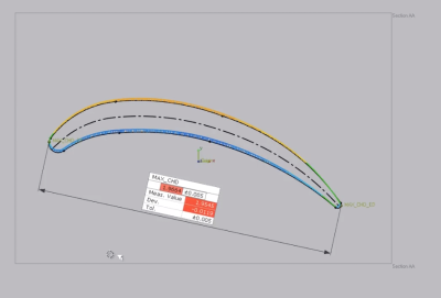
Maximum chord height
Leading (and trailing) Edge position in space relative to the model origin
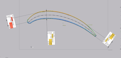
Axial chord length
Additionally, leading and trailing edge thicknesses, as well as maximum airfoil thickness across the widest section, may be easily requested by using this powerful tool. This makes completing airfoil analysis simple requiring only a few clicks of the mouse.
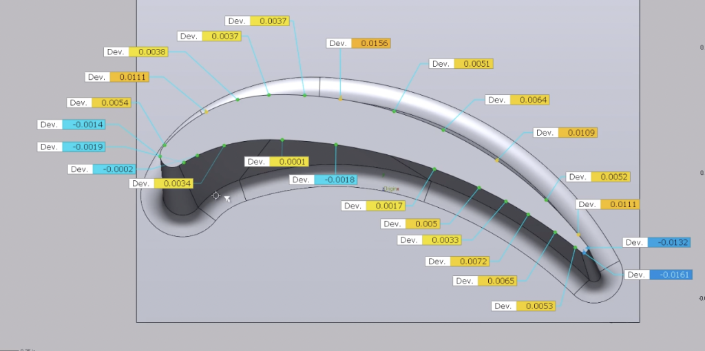
Furthermore, analyzing airfoils often requires identifying points along a section’s periphery and comparing those to the corresponding points from the nominal CAD model. Deploying the Comparison Point function in Control X, this too is handled by just a click or two of the mouse. Please check out our Control X – Comparison Point Analysis video to learn more about how that tool can be utilized.
As you can see, Geomagic Control X continues to deliver incredibly useful tools. Analyzing airfoils can be done in a cinch by using this powerful and user-friendly software. Please be sure to sign up for our 2 Minute Tuesday video series to receive tips and tricks like this one in video form every week. More info at the button below.
Leave A Comment