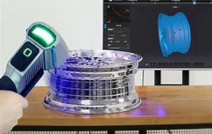
Introducing Shining 3D Freescan UE X7 and X11
Two brand new Shining 3D Freescan scanners called the UE X7 and UE X11 offer a new threshold for high precision scanning combined with a lighter design and enhanced functionality. The enhanced software can import scans into Control X with a single mouse click, completely streamlining the scan-based inspection process. Accuracy for both the UE X7 and UE X11 is an incredible +/-20 microns (+/-.00078”) with an excellent volumetric accuracy of 20 microns + 40 microns/meter while maintaining a maximum resolution of just 50 microns (.0019”). Combining precision accuracy with extremely high resolution, this scanner opens the door for precision scanning of complex parts while still paying attention to very fine detail. Both black and reflective surfaces are now supported by the UE scanner series to minimize, and in many cases eliminate, the need for any type of scanning spray to achieve high-quality scans suitable for rigid metrology applications. The main differentiator between the UE X7 and the UE X11 is scanning speed. Due to the 11 blue crosses used by the X11 as compared to the 7 used by the X7, the scanning speed is an incredible 1.2 million points per second while the X7 still scans at an extremely fast 650,000 [...]

Maximum Material Condition
Why would one want to use a Maximum Material Condition for a true positional callout for clearance holes? Maximum Material Condition or MMC in GD&T is added to the GD&T symbol. The symbol is shown below. In this example, we have a .137 diameter clearance hole that is defined as .137 Rad +/-.010”. Let’s assume the hole is manufactured (drilled) and inspected and it comes out as a .1303 radius, placing it .0067 undersize. There is a True Position callout of .020” for this clearance hole to datums A, B, and C without a Maximum Material Condition callout. By going this route, the dimension fails. The goal of any design is to provide the manufacturing engineer with as much tolerance as possible to still produce a good design that maintains the designer’s intent. If we just go by the True Position Callout for the example above with no MMC specified, the dimension fails and the part would be rejected. If we consider the nominal hole size of .137, the MMC hole based on this dimensioning scheme would be .127” (or .137” minus .010”). This number represents the MMC for this clearance hole based upon the callout. This would represent the hole with the [...]
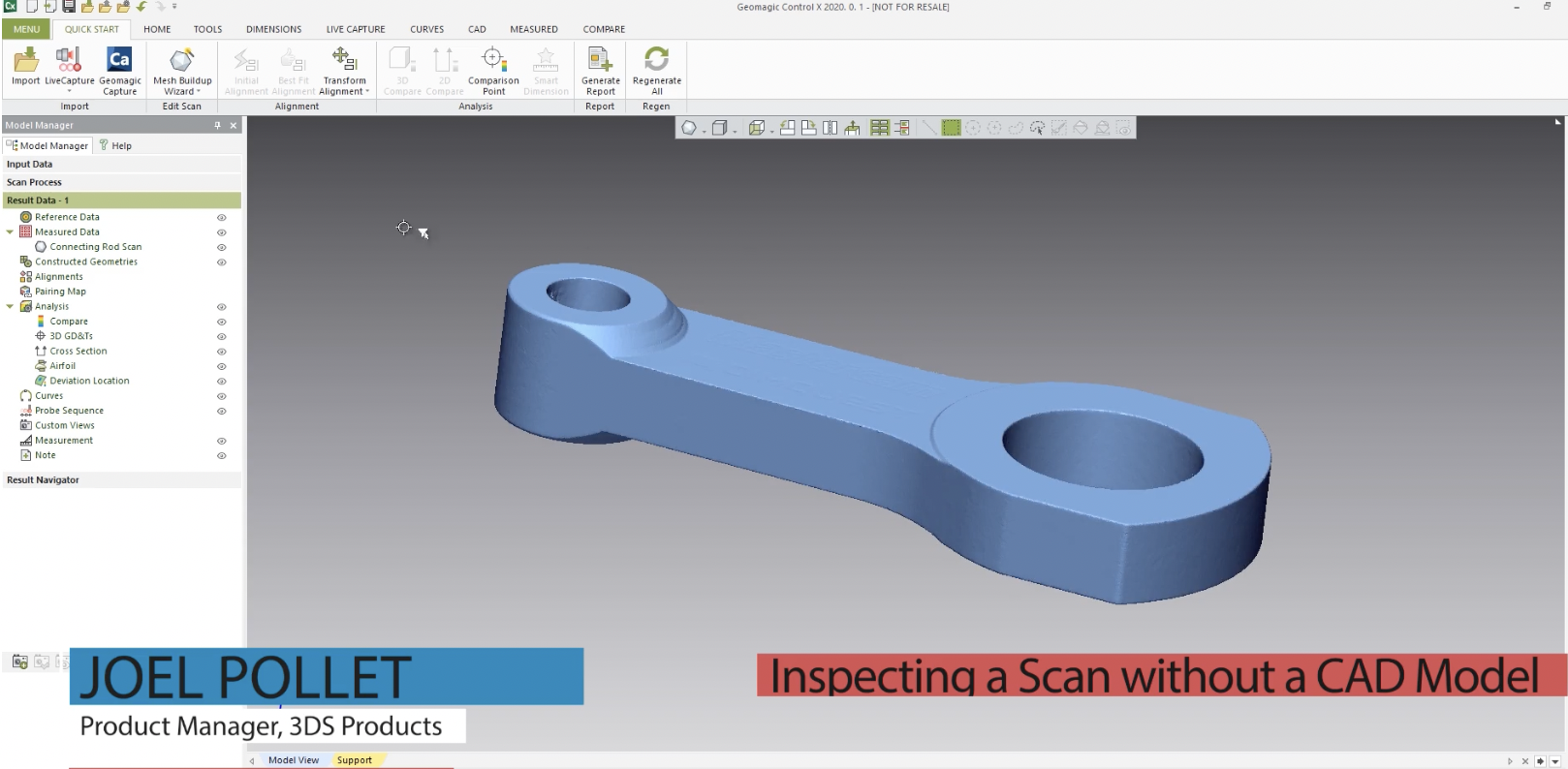
How to Inspect a Scan Without a CAD Model
When using Control X for inspection, you are usually comparing one scan file to another scan file, or a scan file to a nominal CAD file. But sometimes you may have the need to inspect or measure a one-off part without a CAD file to compare it to. This blog post will explain how to take an isolated 3D scan in Control X and take measurements from it. In the example part above we have a connecting arm with only the mesh file. This file will come directly into the measured data node. Normally we would compare it with reference data, but in this case, there is none. When geometry is in the measure data without a reference data we can’t check for measurements. To work around this, we have to transfer it into the reference node. To do this, right-click on the scan and move it to the reference. Once it’s there the Regions functions become active. Now select the scan, select Regions, and click Auto Segment. The software now looks at the model and determines which features are lines, which features arcs, planes, and so forth. If you hover over the geometry, you will see what is a Plane, what is [...]
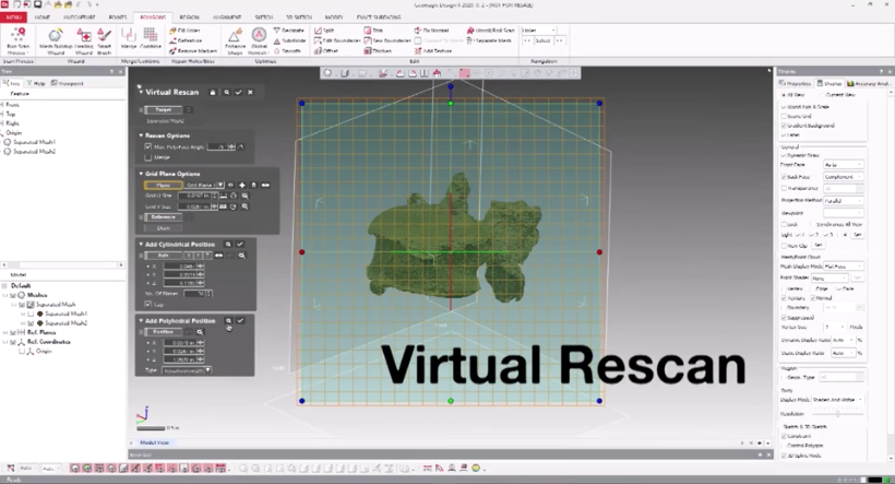
Creating a Water-Tight Model from CAT scan
This blog post will show you an advanced method to clean up internal portions of a CAT scan with the goal of creating a water-tight model. When processing CAT scan data the biggest challenge is cleaning up the geometry. Typically, the internal geometry of a CAT scan contains disconnected poly-faces, which makes it difficult to select and delete only the unwanted geometry. A good example of this is a CAT scan of a bone, as you can see in the image below. This vertebra shows the disconnected poly-faces in what appears to be internal channels and bridges. How would you go about creating a water-tight model from this geometry containing numerous floating, disconnected, irregular objects? Geomagic Design X has a great solution for this. It is called Virtual Rescan. Virtual Rescan recreates a mesh by combining feature shapes captured in the normal direction of each virtual plane. In the settings, you select how the tool will recognize outside geometry, and in essence, it “rescans” to only give you the outside shell. Now, all you would need is to close all the remaining holes and generate your water-tight model. Imagine if you had to do this process manually, selecting and deleting each individual or [...]
Metal 3D Printing for Government and Defense
Encompassing more than 100,000 companies and subcontractors around the globe, the government and defense industries produce everything from equipment for law enforcement, infrastructure and public transit to the development, design, production, and maintenance of military weapons and systems, components, and parts. The mission-critical nature of many of their applications means government and defense manufacturers face a number of unique challenges, starting with production volume. From producing a handful of prototype parts for research to mass-producing a part for field deployment, government and defense manufacturers must be able to quickly move between low- and high- volume production, something that can be difficult - and expensive - for traditional manufacturing processes. To stand up to the harsh conditions they’ll face, including high stress, heat, and corrosion, those parts need to be made from metal - and often alloys with specific composition or performance criteria that can make them difficult to machine. Adding to the challenge government and defense manufacturers face is the fact that projects may last, in some cases, for 70 years or more. Maintaining or replacing parts over decades, however, can be challenging. If the original drawings or tooling is lost, they must be recreated from scratch, a process that is both time-consuming [...]
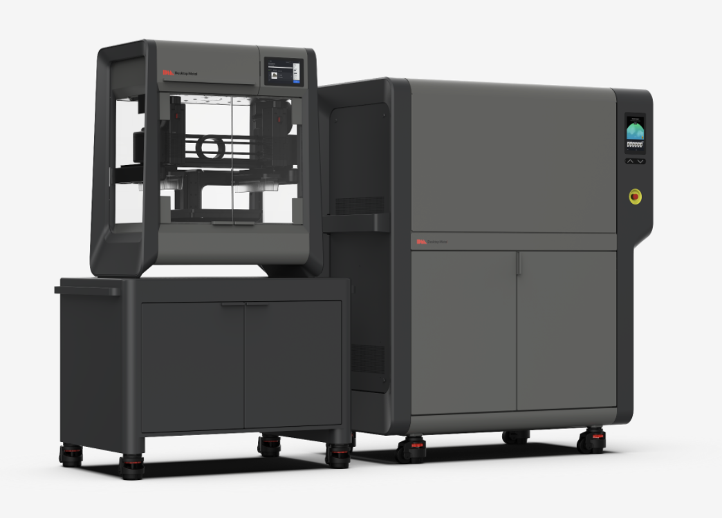
Introducing Desktop Metal Studio System 2™
The Studio System 2 - Office-friendly Metal 3D Printing in Just 2 Steps: Print. Sinter. With a simplified, two-step process that eliminates the need for solvent debinders, The Studio System 2 packs all the benefits of the original Studio System - no hazardous metal powders or lasers, no dedicated operators, no special facilities needs - into a package that’s more accessible than ever before and that produces even higher-quality parts. Using data from thousands of prints, Desktop Metal’s team of engineers and material scientists made significant advancements across virtually all aspects of the system, from material formulations to print/sinter profiles to hardware to the ability to sinter new geometries, all of which add up to improved part success. Along with new material formulations developed for improved surface finish, the Studio System 2 features a specially-formulated ceramic interface, designed to move more uniformly during sintering, reducing the chance of cracking or warping. With new print and sinter profiles built into the system’s software, complicated printing and metallurgical processes are automated, making it easy for Studio System 2 users to produce high-quality parts with improved feature accuracy, surface finish and material properties than Studio System 1 parts. The user-friendly hardware of the Studio System 2 [...]