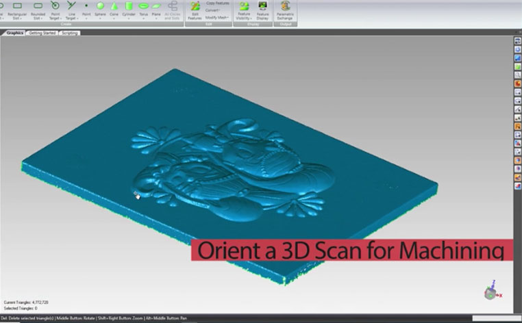
How to Orient a 3D Scan for Machining
In this blog post, we’ll take a look at a scanned part in Geomagic Wrap and show how we can correct its orientation to prepare it for CNC machining. Very often, when we scan parts their orientation is not necessarily known. It could be skewed off plane relative to the angle that the scanner was used when the scans were taken. By cycling through some various orthographic views, you may find that your scan is pretty far out in terms of being square to the plane. In order to take a model like this into Mastercam to generate toolpaths for machining, it would be necessary to square it up. To do that, first, go into the Features menu and hoover over Planes. Wrap has a very useful feature called Best Fit Planes. In this example, we selected the triangles on the top face and then selected Apply Best Fit. This produces a plane that is best fit to the top surface. Using this method, we were able to define several more planes which can be seen under features (shown below). The top plane is labeled plane 1. We also have two side planes, as well as the opposite side plans representing the front [...]
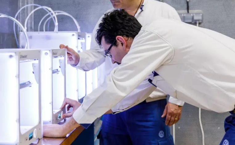
Maximizing Production Efficiency with 3D Printed Tools
Volkswagen Autoeuropa: Maximizing production efficiency with 3D printed tools, jigs, and fixtures Volkswagen Autoeuropa, who is responsible for manufacturing iconic Volkswagen models such as the Scirocco and Sharan, and has yearly output levels of 100,000 cars, now uses 3D printing to revolutionize its workflow. The facility 3D prints manufacturing aids that are used daily on the assembly line. No longer having to rely on external suppliers for its tools, jigs, and fixtures greatly reduces the costs and shrinks lead times from several weeks to just a few days. 3D printed manufacturing aids The case of Volkswagen Autoeuropa illustrates how 3D printing can be of great value to the automotive industry. While - traditionally - 3D printing used to be associated with creating prototypes, it has great potential for manufacturing businesses in creating custom tools, jigs, fixtures, and other manufacturing aids. With 3D printing, it's possible to create highly complex designs and make rapid revisions and amendments, without cost penalties or long lead times. The tools can be tailored to match exact requirements, making function and performance the main drivers of design - not cost or time. This 3D printed wheel protection jig was previously sourced for $950, but can now be printed at [...]
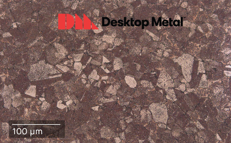
Desktop Metal Releases Pure Copper 3D Printing Material
Now Commercially Available to Studio System Customers Worldwide, Copper Enables High-Performance, Highly Optimized Parts for Oil & Gas, Auto and Consumer Products Industries Desktop Metal recently announced the launch of copper for the Studio System. With its excellent thermal and electrical conductivity, copper is considered an ideal material for transferring heat or electricity and is used in virtually every electronic device made, as well as in many of the heat exchangers used across a variety of industries, including oil and gas, automotive, and consumer products. A key benefit for Desktop Metal customers is that the copper material used with the Studio System is pure copper. Unlike laser-based processes, which often print chromium zirconium copper, the Studio System’s proprietary Bound Metal Deposition process is able to print pure copper, unlocking the full benefits of the material. “Known for its excellent thermal and electrical conductivity, copper is a highly desired material for a variety of industries and applications, such as heat exchangers and electrical components for heavy industries to consumer products,” said Jonah Myerberg, CTO and co-founder of Desktop Metal. “Whether for heat sinks, electrical motor and power grid components, or resistance welding electrodes, 3D printed copper on the Studio System is an ideal choice [...]
Success with Mastercam Swiss Solutions
Two of our Mastercam experts (Rick Bair and Yolexis Lima) recently joined a corporate Mastercam meeting to discuss the success they were having with Mastercam Swiss Solutions. Here is what our experts shared about their confidence in the product, and how it is not only opening the doors to new customers but strengthening relationships with customers already using Mastercam. The following are excerpts from the presentation. Top left to right: Mastercam Swiss Product Specialist Chris Leclerc, Cimquest Director of Mastercam Sales Rick Bair. Bottom left to right: Cimquest Senior Account Executive Yolexis Lima, Mastercam Chief Technology Officer TJ Boberek Rick: I’ve been selling Mastercam for thirty years, and this is the first time that I’ve had a Swiss solution that I feel comfortable with. The Swiss market has been growing tremendously in our territory, so it’s something we definitely need to have. Chris’s knowledge of the Swiss world and machines allows him to be extremely helpful when explaining the Swiss solution to customers and potential customers. Having this Swiss solution keeps us in the conversation with potential customers that have Swiss machines, as well as keeping our existing Mastercam customers from looking at other products for a solution. It’s very easy to [...]

Measuring Features on a Mesh Without a CAD Model
While most inspection software will use a nominal CAD model during the inspection process for comparison of manufactured features to exact CAD features, Control X can perform a feature-by-feature analysis without utilizing a CAD model. This can come in very handy when a CAD model doesn’t exist for inspection and just a 2D drawing is used. The first step is to import just the mesh file or point cloud into Control X. As a reminder, mesh files go into the MEA (Measured) node and CAD or nominal models end up in the REF (Reference) node. Since the system will assume the mesh or point cloud should be the MEA for the upcoming inspection, that is the node where the polygonal file ends up. We need to use the Model Manager and transfer the mesh to the REF node, indicating that no CAD model will be used and just the mesh will be inspected. Next, we need to create Regions on the model so the software can identify features. Once Regions are created, you can measure any of the Region Features as if they come from a solid model and not a mesh or point cloud. Regions are identified by color, as depicted below. [...]
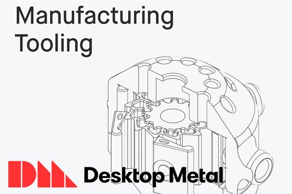
Manufacturing Tooling with Desktop Metal
About manufacturing tooling Tooling is a general term for components used in various manufacturing processes—including machining, injection molding, extrusion, stamping, casting, as well as workholding jigs, fixtures, and end of arm tooling. A single tooling mechanism may consist of several complex parts or one unique part. Tooling is used widely across all manufacturing processes. Though often created in-house by manufacturers, tooling may be outsourced to a specialty tooling shop when complexity or lead time exceeds in-house capabilities. The Challenge When a manufacturer gets a drawing or CAD model for a new product, the first thing that must be done is plan how the part will be manufactured—this plan almost always requires creating tooling. For traditional manufacturing methods, tooling fabrication demands significant non-recurring time, cost, and effort. Both to design the tooling, and then to manufacture it. Once tooling is created and volume production begins, manufacturing lines still need to be maintained, and may often need replacement parts as components wear out or break. To avoid downtime, those maintenance, repair, and operations (MRO) parts need to either be warehoused for immediate use or produced very quickly to get the manufacturing line back up and running as quickly as possible. Many forms of tooling require [...]