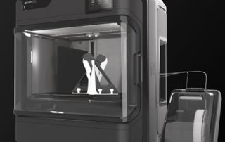
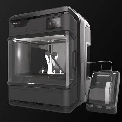
Introducing the NEW UltiMaker Method XL 3D Printer!
Precision printing. Industrial Scale. The Method XL bridges the gap between desktop and industrial printers, providing a perfect fusion of accessibility and performance. Meticulously engineered to create large, accurate parts, this groundbreaking 3D printer utilizes industrial-grade materials that match the precision of industrial production. With its expansive build volume, exceptional dimensional accuracy, and temperature-controlled build chamber, the Method XL can create durable and complex parts with ease. Extra Large Build Volume: Print large engineering parts with ease. Precise Temperature Control: Both the heated build plate and the actively heated build chamber combine to create a stable environment for printing accurate parts of any size. Integrated Air Filters: Exhaust air from the Method XL passes through both HEPA and carbon filters. 5-in-1 Modular Extruders: Quickly change between material groups, preventing cross-contamination. Water-Soluble Supports: Print manufacturing tools and production parts to spec with ABS and a game-changing water-soluble support material that dissolves quickly and easily in tap water. Ultra-Rigid Metal Frame: A structurally-optimized metal frame runs the full length of the body to offset flexing. Less flexing means more consistent prints with better part accuracy and fewer failures. More Details
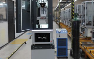
On-Demand Webinar: Mold-Making with DED (Direct Energy Deposition)
Affordable, reliable, safe and easy-to-use metal 3D printer for many applications including mold-making! The Meltio M450 is designed for industry without the need for industrial infrastructure. Ideal for small to medium size part fabrication and multi-metal 3D printing research the M450 is perfect for agricultural, transportation, energy, consumer goods, electronics, aerospace, defense, and heavy industrial markets to name a few. Meltio's Wire Laser Metal 3D Printing is an excellent solution for the manufacturing of conformally cooled molds and dies. Additionally, it's cost-efficient and has the potential to increase performance. Join Meltio's Application Manager, Giorgio Oliveri, for an informational webinar on Mold-Making with DED (Direct Energy Deposition) and Dual Wire, Meltio's specialty. Watch Now Want more general information about Meltio and their open material platform using metallic wire? Visit our website.
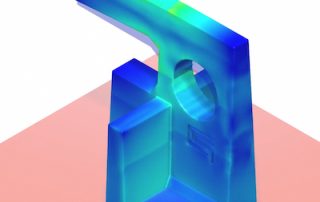
Desktop Metal Live Sinter
Desktop Metal Live Sinter produces quality parts that meet form and dimensional tolerances right out of the furnace, in one or two iterations. Today we’re going to show you an effective way to ensure that metal 3D-printed parts meet form and dimensional requirements right out of the furnace. Although metal 3D printing has many advantages, it can be challenging to predict the final part geometry due to the many physical forces introduced during the sintering process. The part is pushed and pulled in different directions, due to significant forces caused by gravity, friction, and uneven shrinkage due to density variations. This in turn may lead to deformation, warping, cracking, slumping, and parts that emerge from the furnace out of form and out of tolerance. It can quickly become a guessing game. Currently, manufacturers must rely on best practices and the intuition of a relatively few engineers who have hands-on experience with sintering, in an attempt to get good parts right out of the furnace. This can be a time-consuming, iterative process, before achieving the desired results. In contrast, Desktop Metal has taken a different approach. They have developed a first-of-its-kind, multi-physics simulation, and compensation software, that enables one to produce straight, defect-free, and [...]

Metrology Minute – Resizing Section Planes for Custom 2D Cross-Sections
In this issue of our Metrology Minute, we will discuss how to resize section planes so that just the necessary geometry is displayed. This becomes extremely useful for very complex models where you want to draw the reviewer’s attention to a specific location on the model. In order to do this, the first thing we needed to do, in our example below, was to create the plane that we planned to use to create the partial section. We identified these three points first as circle centers and then we fitted a plane through those points as shown below. Next, we placed a point at the center of the large water pump cover radius and created an offset plane, parallel to our construction plane and passing through that point. This is the plane that was used to create the partial section. After we instructed Control X to create the 2D Section, plane control handles became available, enabling us to control just how much of the section was cut by the plane and exactly which cross-sectional geometry was shown. If we wanted to isolate just a single area where the large inlet was located, we could have reduced the size of the plane where just [...]
Freescan Combo 3D Scanner – New Kid on the Block
The Freescan Combo 3D Scanner is a multifunctional, hybrid light source, metrology-grade scanner. The tiny footprint makes scanning of tight quarters much more accessible than with traditional handheld scanners. By having four (4) working modes, the Combo is perhaps the most versatile, handheld scanner, on the market. In Laser mode, it offers multiple laser scanning options; multi-laser scanning (26 crossing lasers), single laser line scanning (for deep holes) fine line scanning (for very high resolution) and infrared (structured light) operations. In Infrared mode, the Combo offers scanning where targets are optional for highly detailed objects or subjects. And while the speed of multiple laser line scanning is 1.86 million points/second, the infrared mode scans at an incredible speed of 2.5 million points/second. Having a total tolerance of just 20 microns (.00078”) and a maximum resolution of just 30 microns (.0012”), this scanner is perfect for high-precision metrology applications as well as reverse engineering, organic scanning and just about any other scanning application. The resolution in Fine Laser mode, where the scanner uses seven parallel laser lines for scanning can achieve incredible levels of detail. Due to the compact size and revolutionary design, the scanner is amazing at capturing fine detail, even ‘seeing’ into very [...]
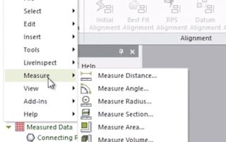
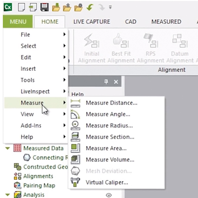
Exploring the Control X Measure Menu
This blog post will delve into the Measure Menu of Geomagic’s Control X software. While most users of Control X are interested in producing color maps, whisker plots, dimension checks, and GD&T analyses of the scan as compared to the nominal CAD model, it is important to note that there are several “mesh-only” functions for measuring a scan model that do not require a nominal CAD model. Geomagic Control X Measure Menu Options The Measure Distance menu simply measures the distance between two points. You just need to keep in mind that the distances are generated from the nearest vertex points on the mesh, not the actual selected point. The Measure Angle menu will measure the angle between two mesh faces, such as the chamfer and body scan below. The Measure Radius menu simply measures the radius of a mesh by selecting three points at the edge of a mesh cylinder. The Measure Area menu measures the surface area of the selected mesh. This measurement is in terms of units squared (for example, in^2, mm^2, etc.). Surface area calculations may be for both closed and open mesh files. The Measure Volume menu measures the volume of a fully closed, manifold mesh. The units [...]