There is a new feature inside of the Analyze Entities function in Mastercam 2020 that makes it easier to figure out associations between geometry and toolpath. This new feature makes it easy to check to see how and where geometry is being used.
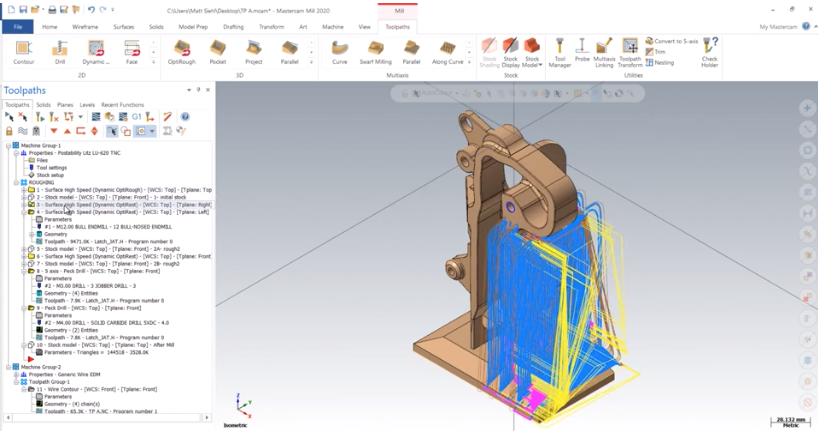
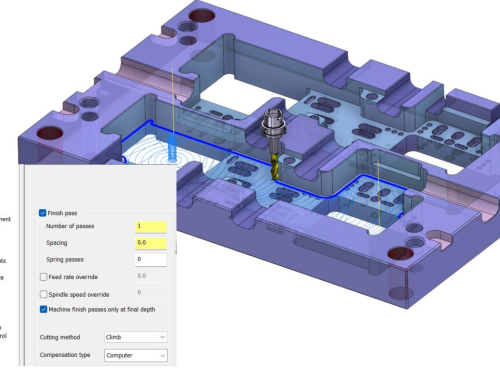
To illustrate, we are going to use a file that has many toolpaths and multiple machines. Most of the work has been programmed for a milling machine, however, there are two features that cannot be milled out. These would have to be completed with wire EDM.
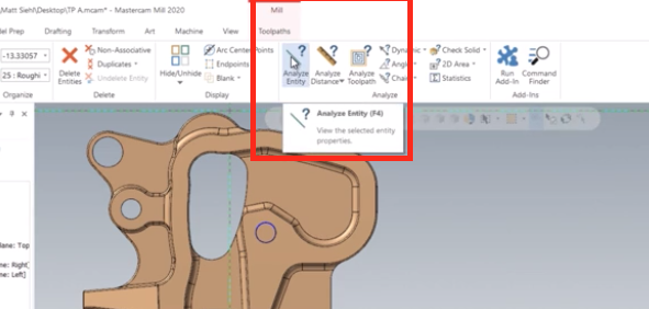
When we begin to analyze some geometry using the icon shown below or the F4 shortcut key shown in the balloon window . . .
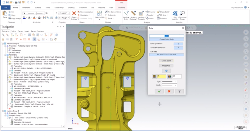
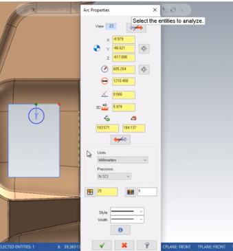
Mastercam will display information about the properties of the geometry that was selected, whether it be wireframe surface or solid.
Dimensional properties, colors, and levels are reported and updated if you continue to select more entities.
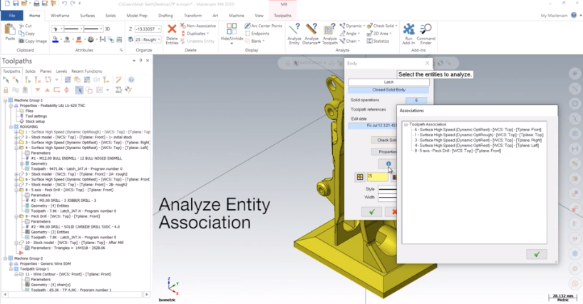
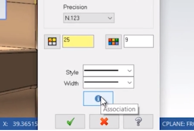
Note that in some cases a new button appears called Association.
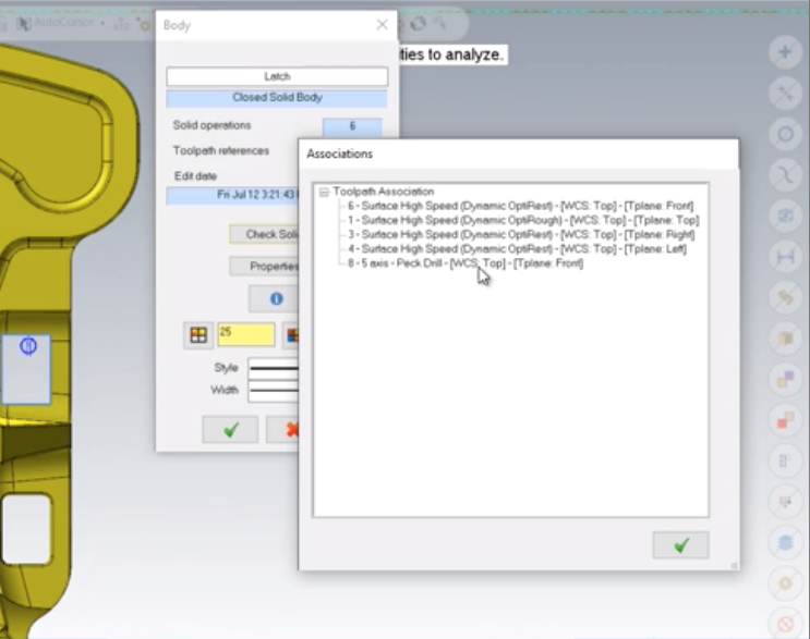
We can use this to see how this geometry is related to the toolpaths. The dialog box below lists all geometry, planes, dimensions, 3D annotations, and operations that are associated with the selected entity.
The solid body shows that it is used in most of the milling toolpaths. The points are used in the drilling operations and for the thread point of the wire contour path. The rest of the wireframe shows that it is used for the Wire process as well.
As you can see, this new feature makes it quick and easy to figure out where geometry is being used, no matter how many toolpaths or machine groups are involved. We can tell exactly what is safe to alter or delete and what’s associated the toolpaths.
Please be sure to sign up for our 2 Minute Tuesday video series to receive tips and tricks like this one in video form every week. More info at the button below.



Leave A Comment