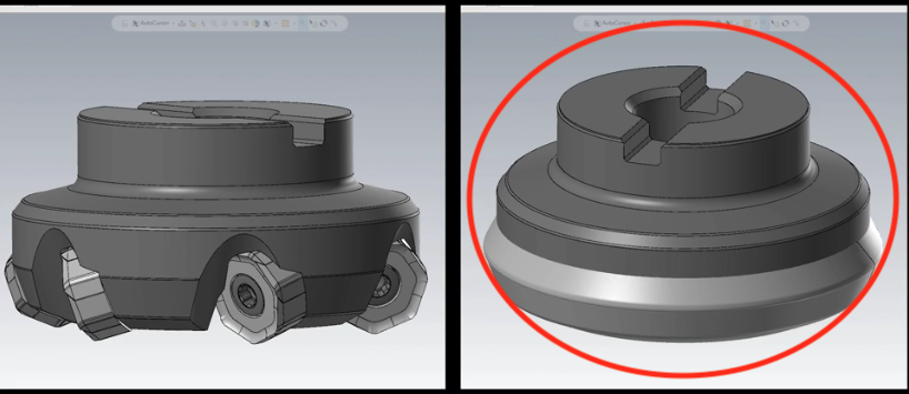
This post will explain how to use a solid model downloaded from the tooling vendor to define a custom face mill profile in Mastercam. When downloading the solid model to define the face mill some of the tooling vendors will offer a detailed and simplified version of the solid models. To define the face mill in Mastercam the simplified model is preferred.
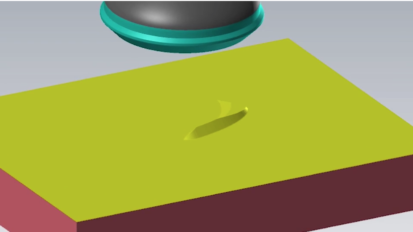
However, if we use the model with the default settings to define the face mill, in many cases when the toolpath is run through the Verify utility, you will notice there is material left behind and the face mill does not cleanup the stock.
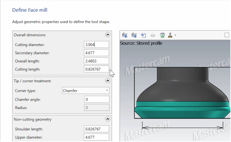
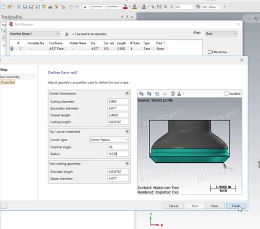
To correct this we need to edit some dimensions for the custom face mill in the Tool Manager.
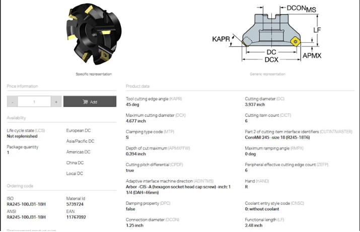
Many of the tooling vendors will have drawing information on their website with the critical dimensions to properly define the face mill. If that information is available it’s a good practice to create a screenshot the page.
In this case, we will be working in Mastercam with a dimensioned DXF file of the face mill.
For the tool path to correctly calculate the compensation of the face mill we need to edit the cutting diameter. This is especially important when the inserts are indexed at an angle. For this tool the cutting radius is 1.9520″ 3.9040″ for the diameter. The chamfer angle can be set to 45 degrees and the corner radius .0390″. The cutting length, shoulder length, and upper diameter can be edited as well, however, those values are not critical to calculating the diameter compensation.
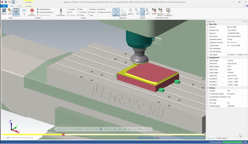
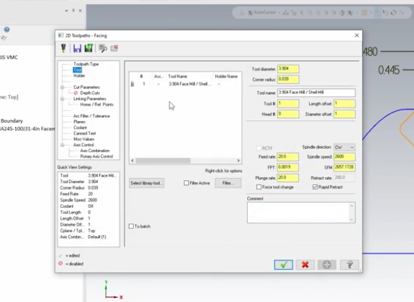
Now the new values loaded are into the tool definition and face mill is associated to the facing toolpath.
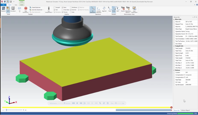
You will see in the Verify utility there is no leftover stock. With the new face mill properly defined don’t forget to save it to your custom tool database for later use.
Please be sure to sign up for our 2 Minute Tuesday video series to receive tips and tricks like this one in video form every week. More info at the button below.




Leave A Comment