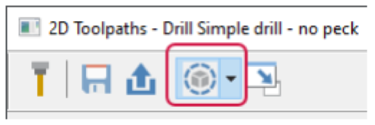
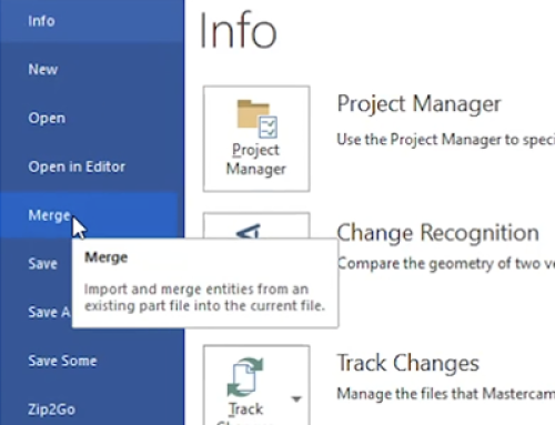
A Display graphical elements button has been added to hole-making and multiaxis toolpath dialog boxes. This control allows you to show or hide graphical elements such as selected geometry colors and graphical planes, depending on the toolpath type.
Mastercam 2024 Viewing Linking Parameter Planes
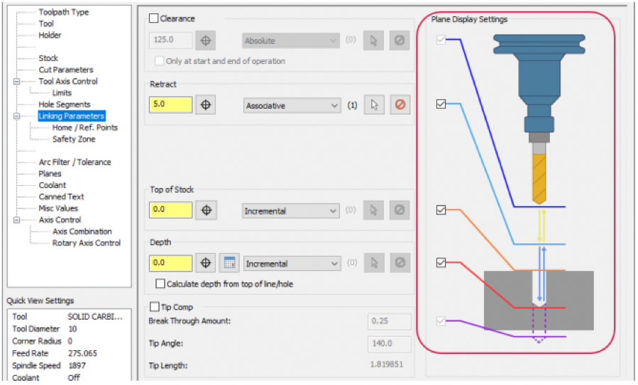
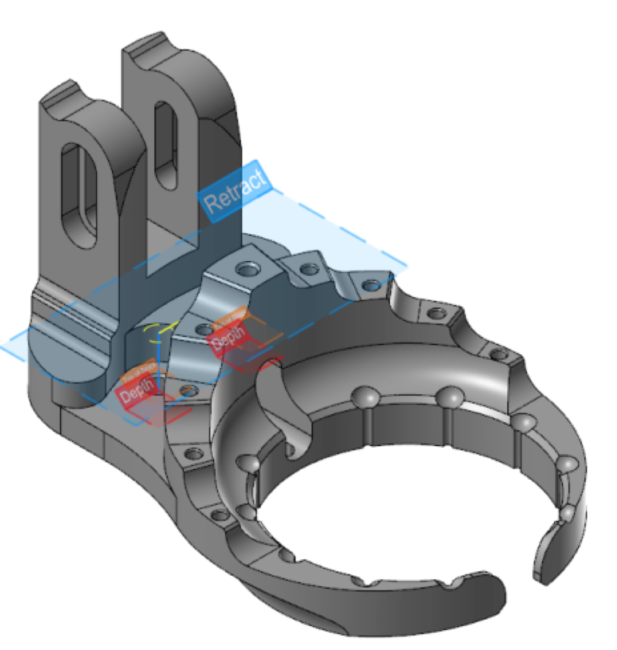
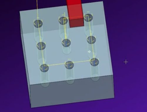
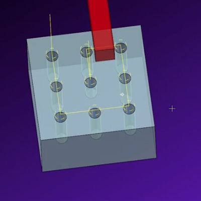
When you create a hole-making toolpath, Mastercam can now display on-screen indicators of plane types and values. Use the Display graphical elements button to turn on graphical elements. Then, in the Linking Parameters page, select the planes whose indicators you want displayed in the graphics window, as shown in the following image.
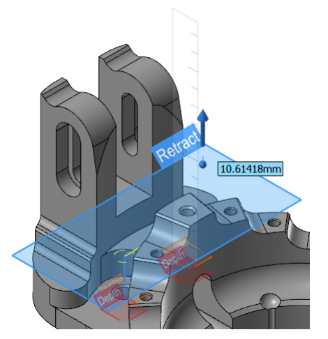
When you change values in the dialog box, Mastercam updates the graphical planes in the graphics window. You can also change the position and value of a plane by dragging its graphical representation in the graphics window, as shown in the following image. During this dragging, you can type a value into the box that appears with the gnomon. Additionally, you can drag the plane indicator to an AutoCursor point.
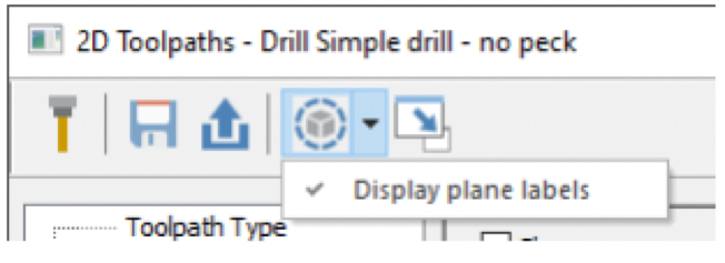
By turning off the Display plane labels option in the Display graphical elements drop-down, you can remove the labels from the plane indicators, leaving you with a simpler display. When the labels are off, you can hover your mouse pointer over a plane to see its label.
Stayed tuned for more info on the upcoming new release!

Leave A Comment