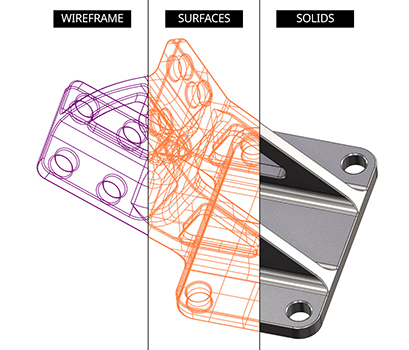
In most cases – and especially when a customer has provided only a description or 2D drawing of a part – the first step in the machining process is to build a digital model of the desired part. This model will be a precise, virtual 3D representation of the part’s dimensions, planes, and contours. In CAD (computer-aided design) programming, there are three main types of models: wireframe, surface, and solid. Each has its own strengths and weaknesses. Follow along as this blog describes what wireframe, surface, and solid models are as well as how to use them.
What are Wireframe models?
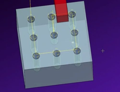
Wireframe models are the oldest of the three listed technologies, but they are by no means outdated. Often the very first model of any machinable part will be created in wireframe. A wireframe model is a digital representation of a 3D object, but only at its edges – specifically, where two contiguous but distinct planes meet. These edges are demarcated by a line as if the design were a metal wire model of the part. Picture the way you would draw a see-through cube. That’s a wireframe model.
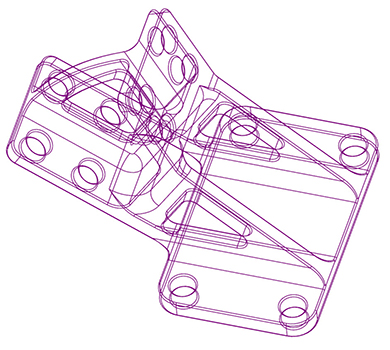
The advantage of starting with a wireframe model is that you can accurately and precisely calculate the underlying structure of a part. Within the Mastercam interface, all wireframe models can be rotated, shrunk, enlarged, and edited with simple mouse-clicks. Wireframe models are exceptionally powerful in highly specific uses of tool control.
What are Surface models?
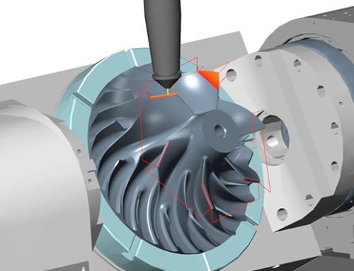
Next in the lineup is surface modeling: more exhaustive than wireframe but slightly more simple than solid modelling. Surface models, unlike wireframes, represent the part’s “skin”. If you spray painted an object and all its cavities, holes, and depressions, the paint would represent the surfaces that cover all the features of the part. However, this model wouldn’t include information about volume, thickness, or how each spray-painted element relates to each other. It is essentially a hollow shell representing the part.
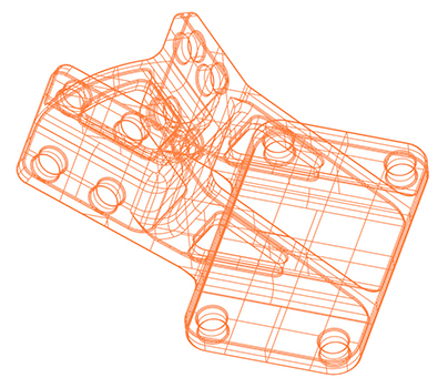
This gives the user an advantage when the external shape needs to be adjusted in a way that would be impossible with a complete solid model. For example, if a part needs its faces built out one by one, surface modeling is the perfect solution because there need not be any other geometry attached to a face. If you were to try doing that with a solid model, you would have to build out multiple faces at once. Surface modeling would give you much more freedom as far as contour and direction. While it is possible to build a complete model using only surface modeling techniques, CAM programming usually relies on a combination with solid modeling. Due to the math behind their construction, there are also some highly complex shapes that are most easily modeled as a surface.
What are Solid models?
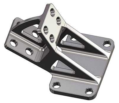
While wireframe and surface models show specific sections of a part, solid models are basically exact replicas of the part in a digital space. This means that its internal features and exact face thicknesses are rendered precisely within the model, as well as the edges and surfaces. A solid model of an automotive motor could be sliced to show detailed cross-sections at any angle. Since solids represent a full 3D version of a part, individual features can be moved, changed, duplicated, or deleted, and the impacted areas will change as well without the need to individually model each section as you would with surfaces.
How are Wireframes, Surfaces, and Solids combined?
Most surface and solid models generally start with some wireframe entity. This first model gives the programmer the advantage of truly understanding the underlying framework of a part. Often, this view will give them the first idea as to how the part will be machined. Note, however, that some solid models will have no wireframe if they are saved off as a “brick.” This will not make the part unmachinable or the model uneditable, though.
From the wireframe model, the subsequent surface or solid model can be built. In cases where some of the design is expressed as a surface model and some is expressed as a solid model, Mastercam allows users to select the two together and machine them as a single unit.
Learn more about Mastercam by clicking below.





Leave A Comment